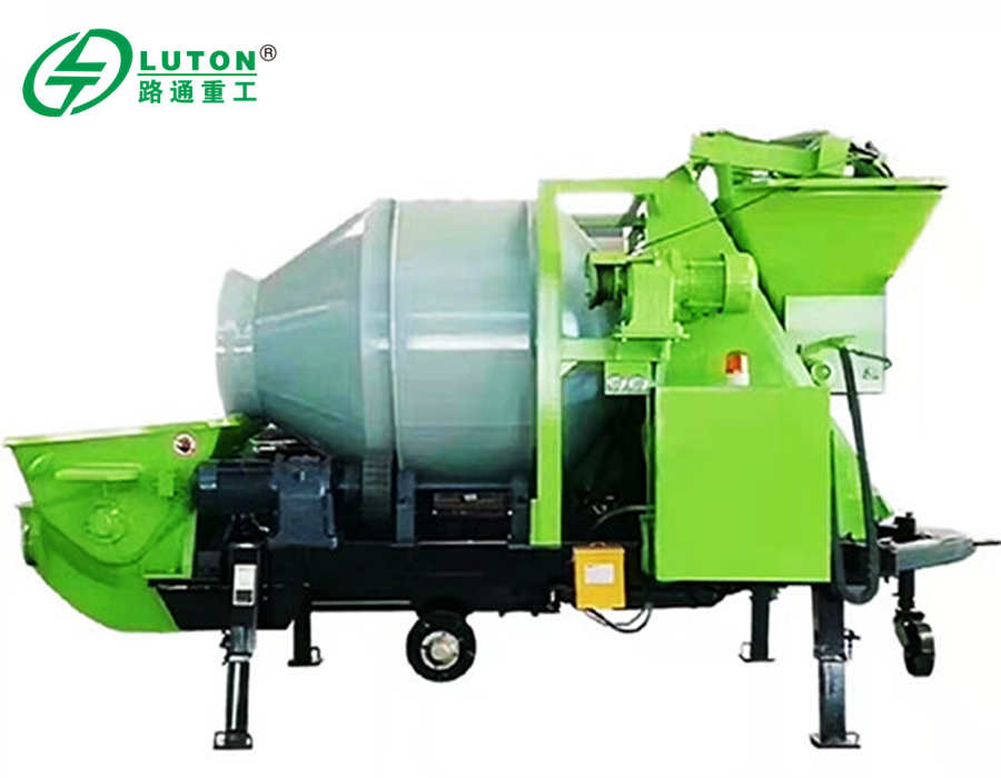
Ready Mix Concrete pump, also known as concrete pump or transfer pump, consists of pump body and conveying pipe.
It is a set of machine that continuously transports concrete liquid along the pipeline by powerful pressure, mainly used in housing construction, bridge and tunnel construction.
At present, ready mix pump is mainly divided into gate valve pump and S valve pump. In order to improve the mobility of concrete transfer pump, the pump body is generally installed on the chassis of a trailer or a truck. And then equipped with a set of pipeline or a retractable boom to form a mixer pump trailer or a boom pump truck.
Brief Introduction to Working Principle of Concrete Pumping System
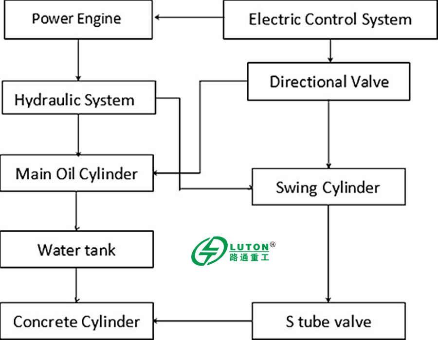
Concrete pump system is composed of hopper, pumping system, hydraulic system, cleaning system, electrical system, motor, walking chassis, etc.
The pumping mechanism consists of two main oil cylinder, water tank, reversing device, two concrete cylinders, concrete hopper, distribution valve (S-shaped valve), swing arm, two swing oil cylinders and discharge port.
The concrete pistons are respectively connected with the piston rods of the main oil cylinder.Under the action of the hydraulic oil of the main oil cylinder, they reciprocate continuously. One cylinder advances, and the other cylinder retreats.
The concrete cylinder outlet is connected to the hopper. One end of the S-shaped distribution valve is connected to the discharge port, and the other end can be connected with the swing arm through the spline shaft, which can swing left and right under the action of the swing cylinder.
When pumping concrete, under the action of the main oil cylinder, the concrete piston 1 moves forward, and the concrete piston 2 retreats. At the same time, under the action of the swing oil cylinder, the S valve is connected to the concrete cylinder 1, and the concrete in the concrete cylinder 1 was pump out the discharge port through the S-shaped valve.
At this time, the concrete cylinder 2 is connected with the hopper. During the backward movement of the concrete piston 2, the concrete in the hopper is sucked into the concrete cylinder 2.
When the concrete piston 2 retreats to the end of the stroke, the reversing device in the water tank is triggered. The main oil cylinder 1 is reversed, and the swinging oil cylinder is reversed.
So that the s-shaped valve is connected to the concrete cylinder 2, and the concrete cylinder 1 is connected to the hopper. Piston 1 moves backwards and piston 2 moves forward. A new working period begins, so as to achieve continuous pumping.
When the pump is working at the reversed mode, the concrete cylinder in the suction stroke is connected with the S valve, and the concrete cylinder in the push stroke is connected with the hopper, so that the concrete in the pipeline is drawn back to the hopper.
The pumping system completes the suction and discharge of concrete through the conversion of the s-shaped distribution valve. Therefore, the s-shaped distribution valve is a key component in the concrete pump, and its type will directly affect the performance of the whole pump.
(Click here to get more details on concrete pumps.)
PLC programming
Next, this article will briefly introduce the application of PLC programmer in concrete pump by taking Siemens S7-200 Smart PLC as an example.
The program development of S7-200 SMART PLC mainly includes motor start-up program, running instruction, proximity switch function, etc.
Motor start
This is the program for starting and stopping the motor. I0.0 is the motor starting signal. By detecting the pulse signal, M0.0 is set, and then conduct the star-type start. At the same time, the timer T37 runs. After 8S, the star-type start turns to the triangle-type. So far, the motor start is completed.
Running instructions
This is the operation instruction of the positive pump and the reverse pump. M3.0 is the middle flag bit that is triggered by the far and near empty positive pump, which drives the Q0.2 positive pump indication. M3.1 is the middle flag bit that triggers the far and near empty reverse pump, which drives the Q0.3 reverse pump indication.
Proximity switch to realize positive and negative pump
This part uses two sensors (proximity switches) I1.0 and I1.1 to detect the opening and closing of the main oil cylinder, and realize the alternate operation of the positive and negative pumps.
The main oil cylinder consists of two sets of hydraulic cylinders and two sets of material cylinders. The main working principle is: the No. 1 hydraulic cylinder drives the No. 1 material cylinder to suck material from the hopper when the pump is running. When the sensor detects that the main oil cylinder is in place, the swing cylinder is controlled by the program to swing to the No. 1 material cylinder, and then No. 1 hydraulic cylinder is used. The cylinder drives the No. 1 material cylinder to push the material, and the material in the No. 1 material cylinder is pumped out through the s valve.